Appendix C
Thrust and Drag Computation
The objective of this appendix is to present a systematic analysis of the thrust-drag bookkeeping in case of an air-breathing propulsion vehicle and to develop the methodology necessary for calculating these forces. The methodology developed in this appendix using control volume approach for the aerodynamic analysis is based on the work done by Cross [1]. At first, we develop a thrust calculation by examining forces within a control volume from freestream to nozzle exit. Using Newton's second law and key assumptions, we derive an expression for uninstalled thrust that considers momentum and pressure effects. Subsequently, we analyze drag components and their interaction with thrust forces during powered and unpowered flight phases.
C.1 Thrust Calculation
Thrust calculation is a crucial aspect an air-breathing propulsion vehicle, as it directly impacts the performance and calculation of aerodynamic drag in powered mode of operation. This section presents a detailed methodology for accurately computing thrust using a control volume approach. By analyzing the forces and momentum changes within the defined control volume, we can evaluate the thrust generated by the air-breathing propulsion vehicle.
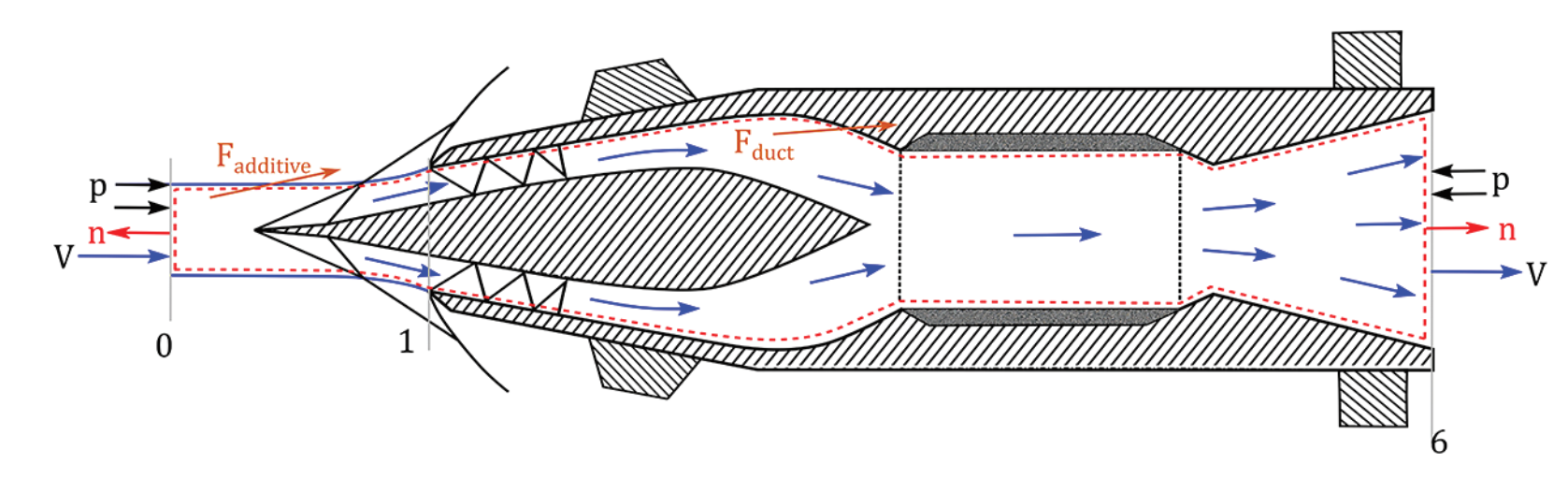
Figure C.1 illustrates an example of an air-breathing propulsion vehicle with important stations marked. The sketch in the figure depicts three main components: a supersonic intake that captures and compresses the incoming air, a combustion chamber where fuel is mixed and burned with the compressed air, and a nozzle that accelerates the hot exhaust gases to produce thrust. The control volume used for thrust calculation is defined by the capture streamtube, which extends from the freestream station (0) to the nozzle exit (6). This volume encompasses the entire flow path of the fluid through the air-breathing propulsion vehicle. Figure C.1 illustrates this control volume with a dashed red line, providing a visual representation of the control volume's boundaries. The thrust vector aligns with the horizontal direction of the air-breathing propulsion vehicle, simplifying the calculations by focusing on forces and velocities in this direction.
Within this control volume, two primary forces act on the fluid. The first is Fduct, which represents the force exerted on the fluid by the internal duct surface. This force accounts for all interactions between the fluid and the vehicle's internal structure, including pressure forces and viscous effects. The second force is Fadditive, which is applied to the fluid in the pre-entry section between stations 0 and 1. This force captures the effects of the flow field ahead of the inlet, including any compression or expansion that occurs before the fluid enters the air-breathing propulsion vehicle.
To calculate the thrust, Newton's second law of motion is applied to the control volume. The net force acting on the system is equal to the rate of change of momentum. This principle is expressed mathematically as:
Here, n is the unit vector pointing outward from the control volume, u is the axial component of the velocity vector V, ρ is the fluid density, and p is the pressure. Assuming uniform values at stations 0 and 6, the surface integrals can be simplified. For the purpose of this analysis, we assume that the vehicle operates at a zero angle of attack, which means that vehicle is aligned with the freestream velocity. This assumption allows us to focus on the horizontal components of forces and velocities, as they are the primary contributors to thrust and drag. Under this condition, the net Fduct and Fadditive force acting on the control volume is expected to be in the horizontal direction. To simplify the thrust calculation, we assign unit-normal vector values of -1 at station 0 and 1 at station 6 in Equation (C.1):
In Equation (C.2), ṁi represents the mass flow rate through face "i", ui denotes the velocity at station "i", pi is the pressure at station "i", and Si is the cross-sectional area at station "i".
In practical applications, the mass flow rate through station 6 is assumed to be approximately equal to that at station 0, neglecting the relatively small contribution of fuel mass flow rate (ṁf). This simplifies the mass flow rate to a single value, ṁ, throughout the system.
The freestream pressure (p0) is commonly used as the reference pressure for calculations, providing a consistent baseline for measuring pressure changes. Incorporating all these considerations, the equation for uninstalled thrust (T) is derived as:
Equation (C.4) encapsulates the net force in the axial direction acting on the fluid within our control volume. The first term, ṁ(u6 - u0), represents the change in momentum flux between the inlet and exit of the air-breathing propulsion vehicle. The second term, (p6 - p0)S6, accounts for the pressure thrust, which arises from the difference between exit and ambient pressures acting over the nozzle exit area. If the fluid at station 6 were to expand completely to freestream pressure (p6 = p0), the pressure differential between the nozzle exit and freestream would be fully converted into kinetic energy. In this case, the thrust would be generated entirely through the momentum term in Equation (C.4), with no contribution from the pressure term.
C.2 Aerodynamic Drag Force
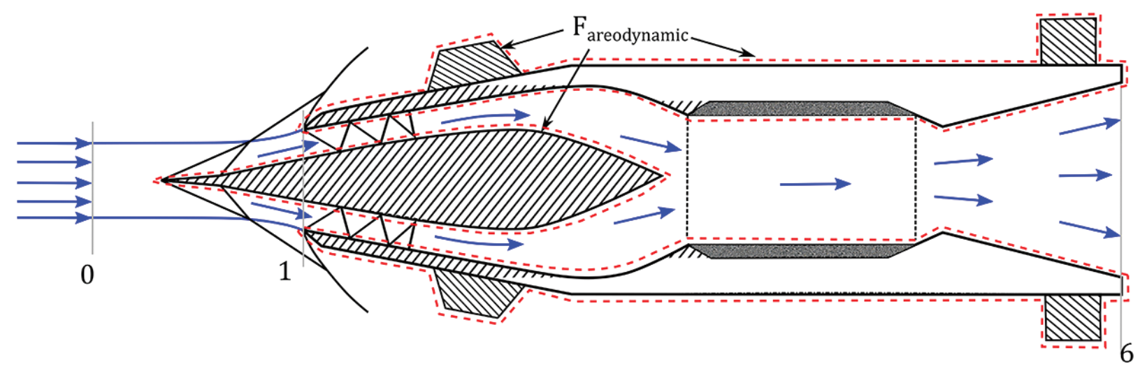
The vehicle experiences a net aerodynamic force (Faerodynamic) exerted by the working fluid over its total wetted surface area, as illustrated by the red dashed line in Figure C.2. This force comprises two primary components: thrust (T), which propels the vehicle forward, and drag (D), which opposes its motion. The relationship between these forces can be expressed mathematically as:
In Equation (C.5), the thrust force acting on the fluid is considered positive. The negative sign before T signifies that the thrust force on the body is equal in magnitude but opposite in direction to the thrust force acting on the fluid within the control volume, as previously calculated in Equation (C.4). The following section provides a detailed description of the various components of the drag force and derives the formula for calculating the total drag force acting on a air-breathing propulsion vehicle.
C.3 Components of Drag Force
To analyze the drag force, we must consider the various components of Faerodynamic, which originate from different parts of the air-breathing propulsion vehicle's structure. The total force is determined by integrating pressure and viscous forces over the entire airframe surface of the vehicle, as highlighted by red dashed line in Figure C.2. The total force can be decomposed into different components based on the contribution from the different parts of the vehicle.
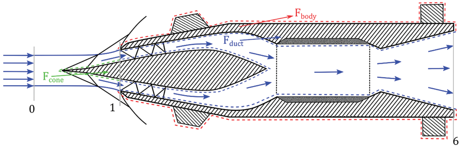
Firstly, we have Fbody, which represents the external pressure and skin-friction forces acting on the external wetted airframe "body" of the vehicle. This component includes the base component as illustrated by the red dashed line in Figure C.3. Secondly, Fduct denotes the pressure and viscous forces exerted by the fluid flowing inside the internal "duct" of the propulsion vehicle, between stations 1 to 6. This is represented by the blue dashed line in Figure C.3. Lastly, Fcone accounts for the forces acting on the external wetted surface of the "cone" (or "ramp" in case of 2D intake) between stations 0 and 1, shown as the green wetted surface in the same figure.
The sum of the forces represents the net "aerodynamic" force, Faerodynamic, acting on the vehicle's body:
So, combining equations (C.6) and (C.5), drag force on the air-breathing propulsion vehicle can be obtained as:
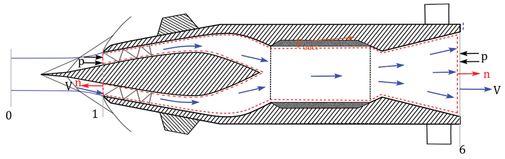
The thrust force can be calculated using the formula obtained in Equation (C.4), however, the calculation of Fbody, Fduct, and Fcone requires integration of shear stress and pressure distribution over the entire wetted surface highlighted using dashed line in Figure C.3. The integration process accounts for variations in pressure and shear stress distributions along the vehicle's contours. This requires detailed knowledge of the vehicle's geometry and flow conditions. Fbody is the force acting on the external wetted surface and can be calculated by integrating pressure and viscous forces over the airframe body's surface. The internal duct force Fduct can be obtained by performing a similar integral on the internal wetted surface or using the control volume, as defined in red in Figure C.4, to find the force applied by the fluid on the internal duct surface. Using the control volume approach, the internal duct force Fduct can be obtained as:
Rearranging, we get expression in terms of Fduct:
The minus sign arises because the forces acting on the internal duct surface are taken as positive, and an equal and opposite force will act on the boundary of the control volume. In Equation (C.9), pref represents the reference pressure, which we typically take as the free stream pressure at station 0 (p0). The integrals account for the pressure differences and momentum fluxes at the duct inlet (station 1) and exit (station 6). We can simplify this equation by considering the area unit normal (1 at exit plane 6 and -1 at station 1) and expressing it in terms of mass flow rate and velocities:
Here, S6 and S1 represent the cross-sectional areas at stations 6 and 1, respectively, while ṁ denotes the mass flow rate of air through the duct. By substituting the expressions for T (from Equation (C.4)) and Fduct (from Equation (C.10)) into Equation (C.7), we can derive a formula for drag.
After simplification, Equation (C.11) becomes:
Equation (C.12) provides a representation of the total drag acting on the vehicle in terms of subcomponents. It accounts for the forces on the external wetted surface of the vehicle's body (Fbody), the forces on the external wetted surface of the cones (Fcone), and the pressure and momentum flux through the interface at station 1. The third and fourth terms on the right-hand side of Equation (C.12), namely (p1 - p0)S1 and ṁu1, collectively represent the force acting at the interface at station 1, which we refer to as the interface force (Finterface). This interface force is illustrated in Figure C.5.
Therefore, the drag force can be represented as:
where,
and
C.4 Operational Considerations and Importance of Drag
It is crucial to understand that the drag calculations presented above are applicable when the propulsion system is operational and thrust is non-zero. During this phase, the ram force term (Fram = ṁu0) is included in the drag calculation due to the presence of thrust. The forces acting on the internal wetted surface, including those on the nozzle, are absorbed into the thrust calculation.
For shell-type projectiles, the drag force holds particular significance. Unlike conventional aircraft or missiles where internal flow efficiency or total pressure recovery might be paramount, shells operate their combustion or engine systems for only a fraction of their total flight time. This means that while thrust acts for a limited duration, drag is a constant factor throughout the entire flight trajectory. Consequently, minimizing the forces that oppose the shell's motion becomes a critical design consideration for optimizing overall performance.
When the shell enters a coasting mode, typically after the propulsion system has ceased operation, the aerodynamic analysis must be adjusted. In this phase, the momentum and pressure forces through the nozzle exit become significant factors and must be explicitly included in the drag calculation. This shift in calculation methodology reflects the changing dynamics of the shell's flight as it transitions from powered to unpowered motion.
C.5 Additive Drag
Additive drag, also known as pre-entry drag [2], is a crucial component of the overall drag force acting on a vehicle, particularly in supersonic flow conditions. This phenomenon occurs when the capture area of the inlet is smaller than the cowl section, resulting in a complex interaction between the incoming flow and the vehicle's geometry. Specifically, additive drag arises when the shock waves generated by the cone or ramps do not meet precisely at the cowl lip, a situation that typically occurs when the inlet is operating at off-design conditions or when the capture area is intentionally designed to be smaller than the cowl section for specific performance reasons.
The net drag on the shell can be expressed as a combination of the airframe body drag and the additional drag incurred due to the mismatch between the capture area and the cowl section. Mathematically, we can represent the total drag as:
And, the pre-entry drag or additive drag (Fadditive) is then given as:
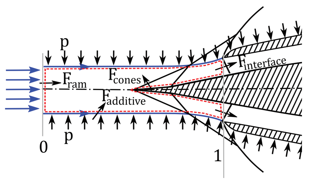
This formulation provides a quantitative measure of the additional drag force experienced by the shell due to the inlet configuration. We can arrive at the same formulation for additive drag by analysing the control volume shown using the red dashed line in Figure C.5.
The boundary streamline of the capture streamtube experiences pressure forces, depicted by black arrows perpendicular to the streamline in the figure. From the freestream conditions to the shock intersection point, these pressure forces balance each other due to the axisymmetric or horizontal nature of the streamtube. However, after the shock intersection point, the streamtube expands and curves. This curvature creates a net force in the axial direction, aligned with the direction of drag. This additional drag force, resulting from the streamtube's curvature, is what we refer to as the "additive" drag force. It is important to note that the additive drag force would be zero if the cowl lip were positioned exactly at the shock intersection point, though this ideal condition is rarely achieved in practice, especially across a wide range of operating conditions.
When calculating the additive drag force (Fadditive) using the integration of pressure force over the boundary streamline shown in Figure C.5, the total drag force can be calculated using Equation (C.16). The additive drag subsumes cone/ramp, interface and ram force components and they do not need to be accounted for separately.
References
- Cross, P. G., "Force and Moment Accounting Procedure for Vehicles With Air-Breathing Propulsion Systems," NAWCWD TM 8907, NAVAL AIR WARFARE CENTER WEAPONS DIVISION, China Lake, CA, May 2021.
- Faro, I. D. V., "Supersonic Inlets," AGARDograph 102, AGARD-NATO Fluid Dynamics Panel, May 1965.